FAB ACADEMY FINAL PROJECT
My final project start with a previus studie about minimal forms.
I want to re-create my Architecture Final Project with a new kind of structure and tensile mesh. I want that it moves depending of the amount of sun that receive. It will not be only a "dress" it will be the adaptable building's protection.
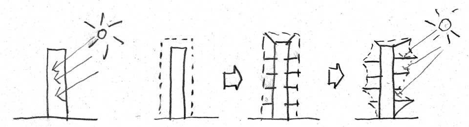
In my final year of Architecture I made several models, which helped me better understand the operation of the textile architecture and minimal surfaces.
After the models did parametric models using Rhinoceros and Grasshopper, I finally ended up doing renders with Vray Rhinoceros.
After the models did parametric models using Rhinoceros and Grasshopper, I finally ended up doing renders with Vray Rhinoceros.

FINAL PROJECT
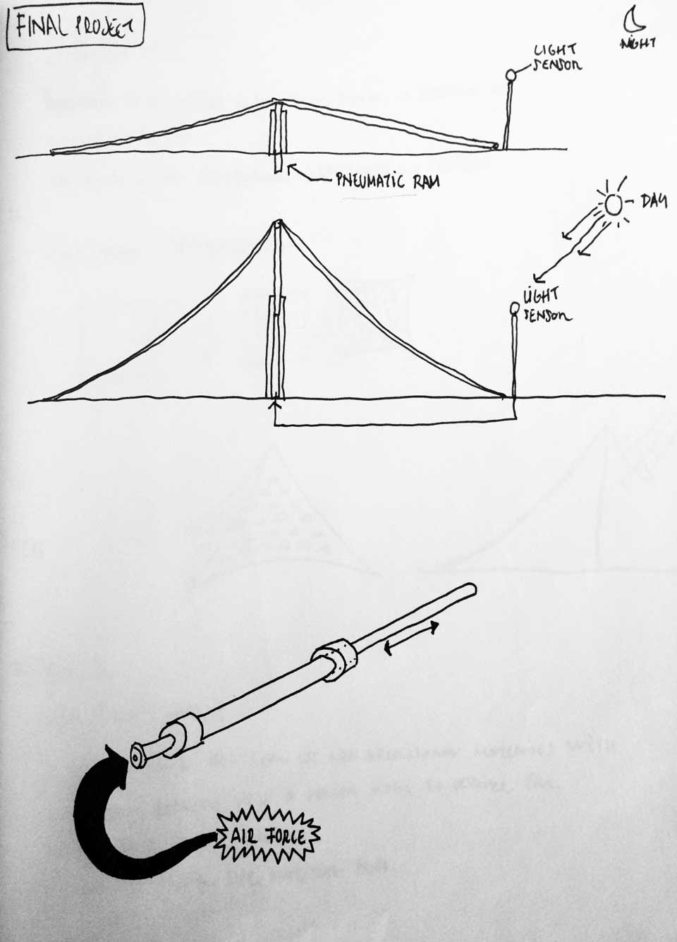
I want to build a new model that can be adaptable to changing amount of solar radiation. I can get it with a light sensor and a mobile mast.
I think in made it with a pneumatic ram, but maybe it's easier with a endless screw.
IDEA
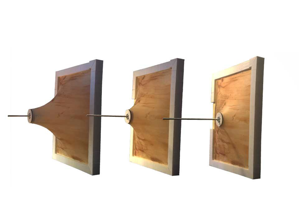
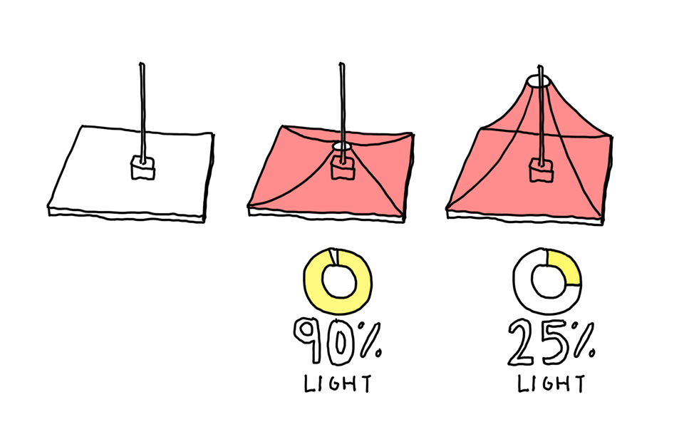
I have a base to cover, for which I use a mast (spindle) and a surface (latex)
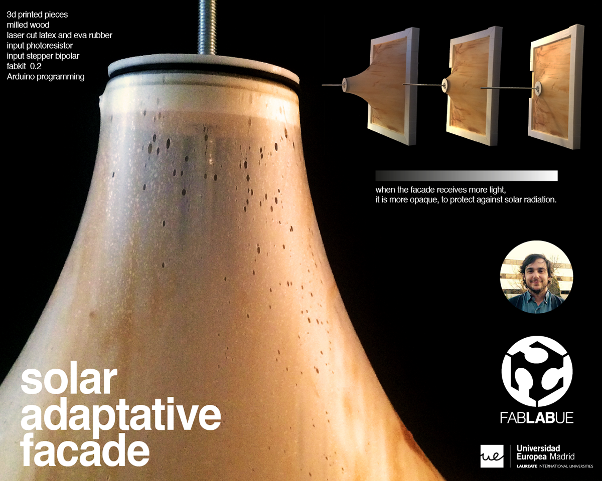
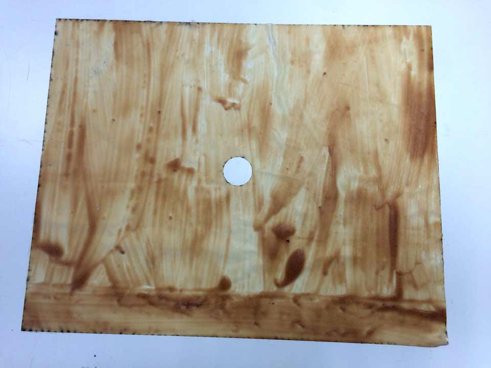
By stretching the surface lets more light to lose section. In addition, the latex has a micro holes produced by air bubbles when I made it. These holes let in even more light.
By stretching the surface lets more light to lose section. In addition, the latex has a micro holes produced by air bubbles when I made it. These holes let in even more light.
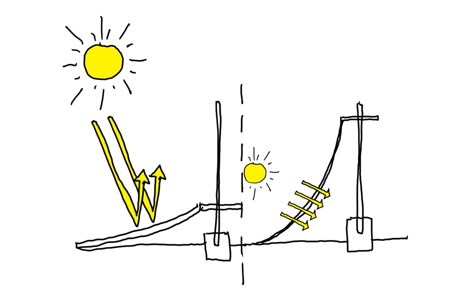
HOW DOES IT WORK?
When the light is higher the facade will be lower, protected from light, when there is less light, the structure will rise, allowing more light path.
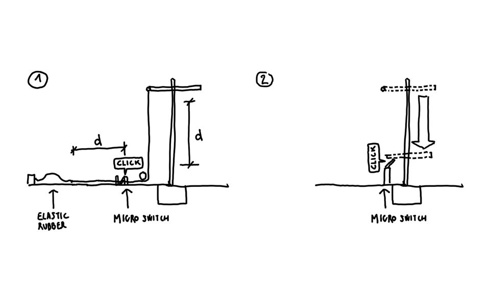
The first idea was to use a pulley system with a limit switch. The system is simple but could have many faults by depending an elastic rubber at the end of the rope. Therefore I kept thinking about how to fix it.
The solution was to simplify the process. Where is held the latex says what can go up and down the facade. So the solution was to put the limit at a low point before colliding with the motor base.
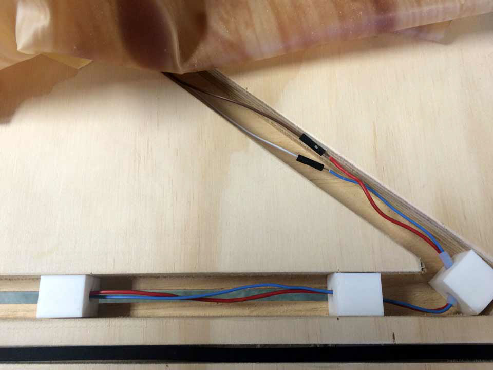
To be able to down the entire system decided on the base had rails, where the cables are accommodated. Besides the engine would be embedded in the base.
MOVEMENT AND SENSOR. PROGRAMMING.
The idea is that the system always starts at the same point (micro switch). When the system is turned on it will find the lower limit. When it find it, all the system wait for 3 seconds (delay).
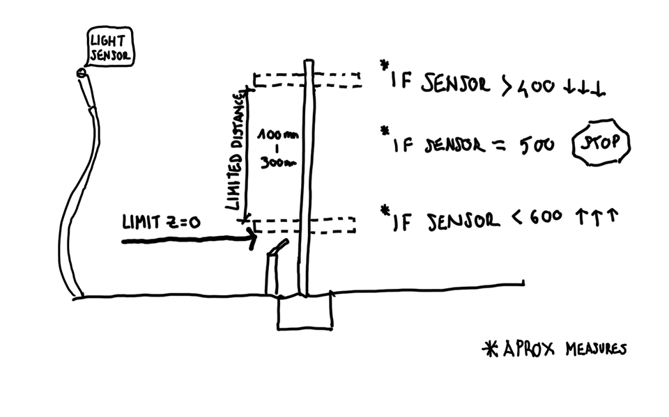
Then the light sensor is activated. When the amount of light is less than 600 facade ascend. As there is no race to the other end of the spindle I have limited what goes up:
1 mm = 200 steps
100mm = 2000 steps
1 mm = 200 steps
100mm = 2000 steps
When the amount of light is higher than 400 the facade descend.
When the amount of light is equal than 500 the system stop.
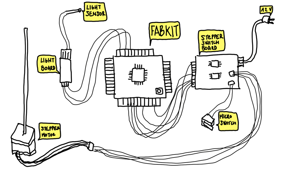
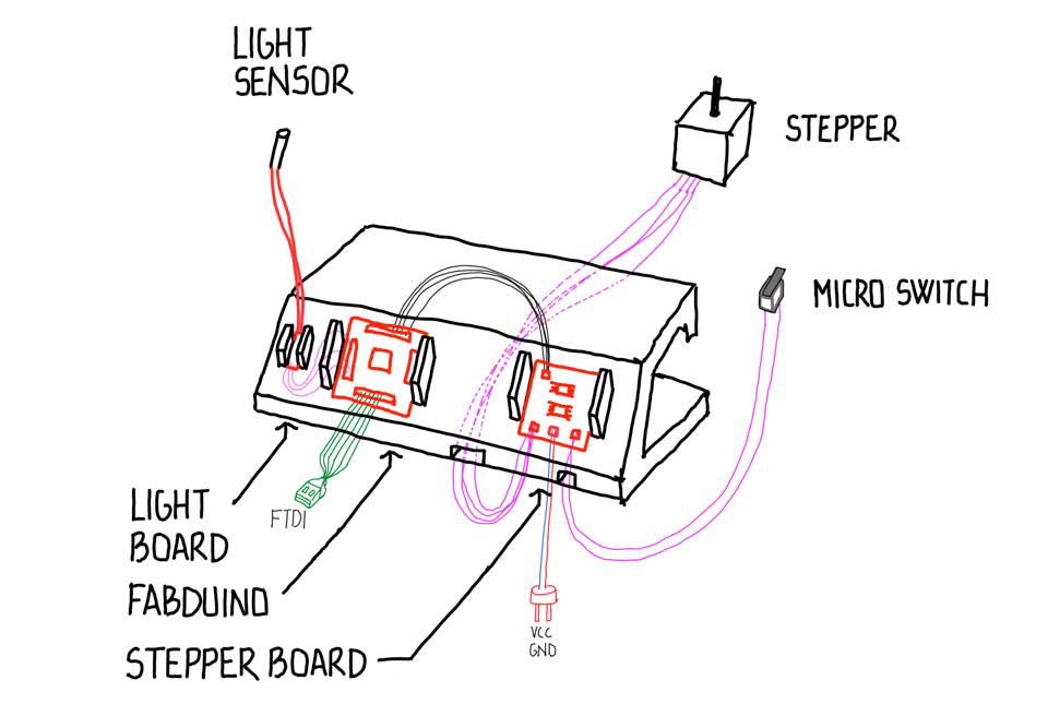
BOARDS SYSTEM
This is an outline of how the different boards are connected.
PIECES
BASE. Milled wood. I have used 6mm mill. I have used two routines. Axis profiling and axis pocketing. The first thing I need to make holes that cross the wood because the wires going under so I make an axis profiling. I select the curves I need to make the holes.
The small exterior rail is to hold the latx (see latex base holder) and the interior pocketing is to stock the cables. The base is raised to pass cables below. For this I designed the Base Holder Latex.

LATEX SURFACE. At first I wanted to use a fabric but I decided to make everything I could for my final project, so I decided to make a thin layer of latex to hang on the efforts of the movement of the project. I have made some test (week 12 molding and casting).
To hold the latex to the base I need a 3d piece that fit into a rail made in the base wood. Also I designed a 3d piece to hold the latex witn the spindile.
LATEX BASE HOLDER. I need to hold the latex with a piece. I designed the piece to fit the outside rail of the wooden base. I've also added a hole if enough grip was not optimal and hold the piece with chipboard screws. (It has not been necessary) To prevent the latex scratch, I used rubber eva.
To hold the latex firts I use a tape.
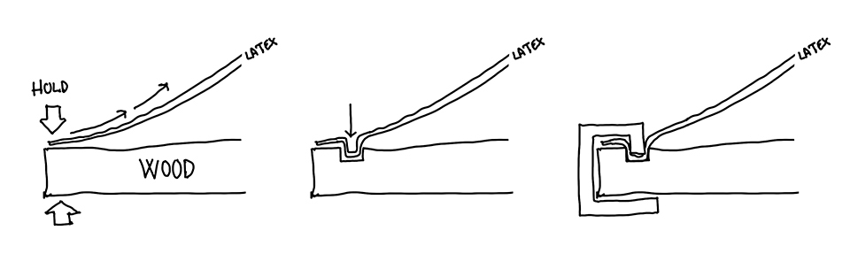
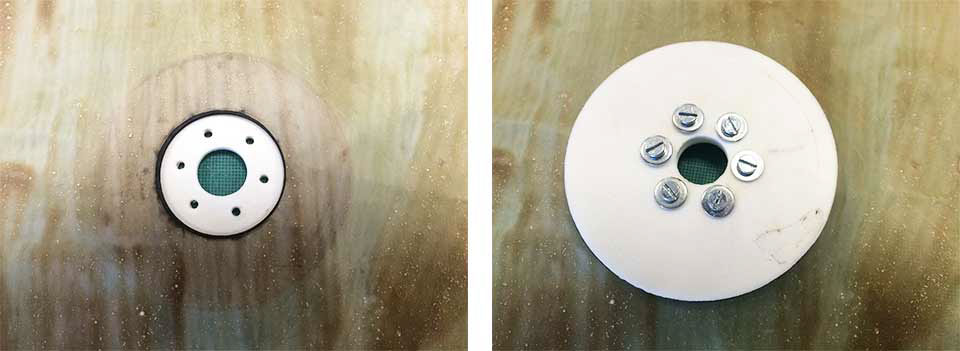
LATEX BRACKET. I need to hold the latex with a piece. I need two pieces to hold the latex. To tight the piece I use six screws. To prevent the latex scratch, I used rubber eva.
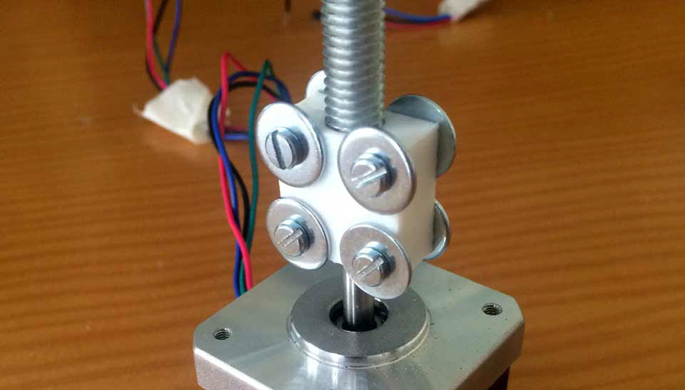
SPINDLE NUT PUSH. On top of this piece is the Latex bracket.. I have attached a nut which is hosted in the spindle.

SPINDLE HOLDER. This piece join the splindle with the stepper motor Nema 17. I need screws, nuts and washers for proper hold.
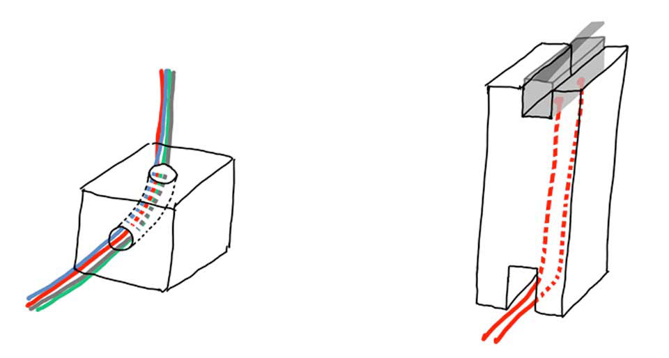
MICRO SWITCH HOLDER and CABLE HOLDER PIECES. To attach the micro switch I created a hollow part so they can pass the cables. For those cables do not move I designed pieces to have them holded. These parts are attached inside the base to prevent touch the surface of latex.
ELECTRONICS HOLDER. This is the last piece in 3d that I design. This work is hold my three electronics boards. First I think in print a very large piece, but finally I prefer print three differentes so I can pass the cables between them.
TESTS
CONCLUSION / FUTURE
Use boards manufactured by self brings many problems, but also made me learn things before the Fab Academy did not imagine that I could learn. Despite having no previous knowledge of electronics I have come to understand how a microchip works.
With a longer course could have learned much more so in the future I will study more about electronics and programming.
With a longer course could have learned much more so in the future I will study more about electronics and programming.
The future development of the project is clear. I would like to build something more complex, and the next step is to do a larger scale. Later I would like build smart buildings that react to external actions, like light, wind, rain, and why not? feelings of its members with inputs, outputs...
special thanks to:
Sergio Bemposta, Javier Prado, Germán Colomar, Luis Soliverdi and FUEM guys, Alborán Fatou, Sara Núñez, Fabricio Santos, Marta Verde and Nuria Robles
FOR MORE INFO, FILES, ELECTRONICS SCHEMES, ETC: